Connector Contact Resistance and Long-Term Heating
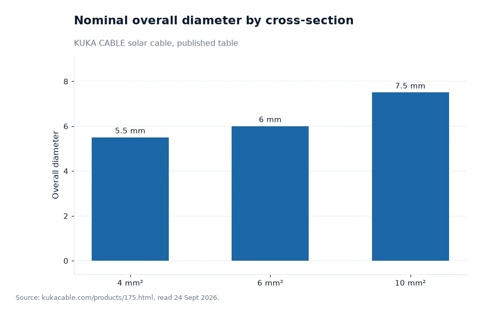
Contact resistance is the extra resistance created where two metal surfaces meet, and at a mated pair on a PV string it turns a small part of the current into heat year after year. KUKA CABLE sells a solar cable connector range alongside its DC cable family, and the data its own pages publish for the cable is where a check has to start: the 4 mm² size measures 5.5 mm across, the 6 mm² size 6.0 mm and the 10 mm² size 7.5 mm.
Key takeaways
- A joint heats in proportion to the square of the current, so the same contact resistance costs four times the watts when the string current doubles.
- Published diameters are 5.5 mm at 4 mm², 6.0 mm at 6 mm² and 7.5 mm at 10 mm², and each one decides which connector body and sealing gland will fit.
- Conductor heat has two published ceilings: +120 °C may be held for 20,000 hours, while +250 °C is allowed for 5 seconds only.
- The manufacturer's own test list includes cable connectivity and construction plus dimensional testing, so a joint can be asked about without waiting for a fault.
Where contact resistance comes from in a mated pair
Two clean metal surfaces never touch across their whole area. They touch at a scatter of high points, and the current squeezes through those points, so the joint behaves like a short length of very thin conductor. Pressure, surface finish and the absence of oxide decide how tight that constriction is.
Tinned copper helps on the cable side, because the tin layer keeps copper oxide away from the interface. A connector contact is usually plated for the same reason. What spoils the joint is a crimp that was made with the wrong die, a contact that was pushed home only part of the way, or grit and moisture trapped between the surfaces before closing.
The client's pages do not publish a milliohm figure for connector contact resistance. A buyer who needs one has to ask for it, and the useful form of the answer names the test current and the number of mate and unmate cycles that go with it, because a resistance figure without those two conditions cannot be compared with anyone else's.
Heat, copper and two published temperature limits
A joint that adds resistance sits in series with the cable, so the losses in it add to the losses in the copper. Power lost in a resistance rises with the square of the current, which is why a string that is extended and re-fused often runs warmer at its plugs than at its middle.
For the cable itself, the manufacturer publishes an ambient range of −40 °C to +90 °C, a short-circuit allowance of +120 °C for 20,000 hours and +250 °C for 5 seconds. A hot joint pushes the conductor towards those ceilings from the inside, and a joint is the one part of a string that degrades with time instead of simply carrying load.
The 1500 V solar cable is tested on the finished product at 6.5 kV AC, 50 Hz, for five minutes, and it passes a 10 kV spark test during production. Those tests catch insulation faults; they say nothing about a contact that will loosen in the field, which is why the assembly step belongs in the same quality system as the extrusion line.
The cable itself is named against TUV 2PfG 1169/08.2007, EN 50618:2014 and IEC 62930, and TUV certification is described by the manufacturer as the starting point for a PV cable rather than the finish, with the certificates page listing more than 30 certificate types in total.
Why the cross-section decides the connector you can crimp
A connector body is machined for one range of conductor sizes, and the cable's outside diameter has to fit the sealing gland at the back of it. That is why the published diameter table matters before a single plug is ordered: the same family of contacts may accept 4 mm² or 6 mm², but the gland and the strain relief are chosen from the millimetre figure. The solar cable connector range on the manufacturer's own site covers MC4 style contacts, solar fuse connectors, solar diode connectors and finished PV cable assemblies, and one of those pages carries a CE and RoHS certificate download.
Stranding is the second half of the match. The 6 mm² conductor is 84 strands of 0.29 mm and the 4 mm² conductor is 56 strands of the same 0.29 mm wire, both class 5 flexible to IEC 60228. A flexible core compresses well under a correct crimp, and badly under a crimp die intended for a rigid conductor.
- Check the conductor size range printed on the connector data sheet against the cable size you are buying.
- Check the gland diameter against the published overall diameter, not against a nominal size.
- Check the crimp tool and die against the contact, and keep the tool's calibration record with the batch.
- Check the mating pairs on one string come from the same system, because contacts from different systems may close but rarely at the same pressure.
The published diameter table
The table below lists the stranding, the outside diameter and the minimum bending radius for the sizes most often used with connectors. The last column is my own arithmetic, 4 times the published diameter, and it assumes one bend at room temperature with no tension on the cable.
| Nominal cross-section | Conductor construction | Overall diameter | Bending radius (author's calculation) |
|---|---|---|---|
| 1.5 mm² | 39 × 0.25 mm | 4.6 mm | 18.4 mm |
| 2.5 mm² | 49 × 0.25 mm | 5.0 mm | 20.0 mm |
| 4 mm² | 56 × 0.29 mm | 5.5 mm | 22.0 mm |
| 6 mm² | 84 × 0.29 mm | 6.0 mm | 24.0 mm |
| 10 mm² | 142 × 0.29 mm | 7.5 mm | 30.0 mm |
| 16 mm² | 238 × 0.29 mm | 8.8 mm | 35.2 mm |
Notice how little room the diameters leave between sizes: 4 mm² and 6 mm² differ by half a millimetre on the outside. A connector ordered for the wrong one of those two will still slide on, which is exactly why the diameter figure belongs on the purchase order next to the cross-section.
Worked example: what a joint costs in watts
Assume a mated pair adds 0.5 mΩ to a string, and treat that figure as an assumption rather than a published value, because the manufacturer's site does not publish a contact resistance. If the string carries 30 A, the loss in that joint is 30 squared times 0.0005 ohms, which is 0.45 W by my own calculation.
The same joint on a 15 A string loses 0.11 W, and on a 45 A string it loses 1.01 W under the same assumption. That is the arithmetic behind the rule that long strings and large cross-sections deserve a closer look at every plug, because the watts grow with the square of the current while the contact stays the same size.
A single watt is not a fire. The problem is the direction of travel: a warm contact oxidises faster, oxidation raises the resistance, the higher resistance makes more heat. The published short-circuit figures of +120 °C for 20,000 hours and +250 °C for 5 seconds describe what the insulation can absorb, not what a connector should ever be allowed to reach in normal service.
Frequently asked questions
Does a mated connector really add resistance to a string?
Yes. Metal surfaces touch at a scatter of high points rather than across the full face, so current is forced through a narrow path at each point and the joint behaves like a short, thin piece of conductor. Pressure, plating and cleanliness set how wide that path is. The manufacturer's site does not publish a contact resistance figure for its connector range, so ask for the value together with the test current and the number of mating cycles behind it.
How much does a warm joint actually cost?
Assume a mated pair adds 0.5 mΩ, which is an assumed figure and not a published value. At 30 A the joint then dissipates 0.45 W by my own calculation, at 15 A it dissipates 0.11 W and at 45 A it dissipates 1.01 W. The square law means the loss grows faster than the current, and since heat speeds up oxidation, resistance rises with temperature once the process starts.
What to ask a supplier before the order
Request four documents: the cable data sheet for the exact size, the connector data sheet with its conductor range and gland diameter, the crimp tool specification, and the test report covering the finished assembly. Then compare the printed diameter with the published cable figure rather than with the nominal size.
The manufacturer describes its laboratory as working to ISO/IEC 17025 and runs a quality model it calls SIF, with 100% inspection of finished products and sample retention for traceability. Its published test list names cable connectivity, cable construction and dimensional testing, and a water resistance test, all of which touch on the parts that decide whether a joint stays cool. Free samples and data sheets can be requested through the site; prices, minimum quantities and lead times are not published there and come back on a quotation.
Figures in this piece on connector contact resistance are the manufacturer's own, taken from its website, and the diameter table was surveyed 24 Sept 2026[1].